Esp12 Pinout

Esp12 pinout
The ESP8266 has 17 GPIO pins (0-16), however, you can only use 11 of them, because 6 pins (GPIO 6 - 11) are used to connect the flash memory chip. This is the small 8-legged chip right next to the ESP8266.
What pins for wemos D1 mini?
Wemos D1 Mini development board has a total 16 pins in which 12 pins are active, uses ESP-12 module, onboard reset button, 3.3 voltage regulator, Micro USB, USB to UART bridge and some other components. D0 to D8, Input/output pins also used for SPI and I2C, Flash. UART interface.
How do I program esp12 F?
ESP-12F: ESP8266 Module - Minimal Breadboard for Flashing
- Step 1: Parts Needed.
- Step 2: Mount the Power Supply on the Breadboard. ...
- Step 3: Wire the ESP-12F on the Breadboard. ...
- Step 4: The Minimal Circuit. ...
- Step 5: What the Breadboard Should Look Like. ...
- Step 6: Real Wiring. ...
- Step 7: First Program. ...
- Step 8: Select Board.
What is the use of the TX pin in ESP 32?
UART on ESP32 On the ESP32, 3 UART buses are available: UART0, UART1 and UART2. We can use them to communicate with a sensor, an Arduino, a Raspberry Pi, a computer … The UART0 is by default on pins GPIO1(TX0) and GPIO3(RX0) of the ESP32. It is used to communicate with the computer through the serial monitor.
How do I use ESP8266 GPIO pins?
Now, connect the ESP8266 using these instructions:
- VCC will be connected to the 3.3V power supply.
- GPIO0 and GPIO2 are general purpose digital ports.
- Rx: Goes to Arduino pin0 (But needs a voltage adjusting)
- CH_PD: Chip enable. ...
- RST: Reset. ...
- GND is ground.
- Tx: Goes to Arduino pin1.
Which pin is VCC in ESP8266?
| Module Pin | Arduino Pin | Name |
|---|---|---|
| 1 | 3 | RxD (GPIO3) |
| 2 | VCC | |
| 3 | 0 | GPIO0 |
| 4 | RESET |
Can I power D1 Mini from 5V pin?
5V Pin: If you use an external power supply like a battery or laboratory power supply, you can use the VIN pin. The voltage must be between 4.3V and 6V. Therefore you are able to power the WeMos D1 Mini with a LiPo battery with JST connector in combination with the battery shield for the WeMos D1 Mini.
Which pins of D1 Mini can be used for I2C protocol?
Using I2C connections with the WeMos D1 Mini (ESP8266) To connect something to the I2C bus you will need to join both devices SCL and SDA pins together.
What can I do with a WeMos D1 mini?
Wemos D1 Mini based home automation system that can control electrical devices like lights, fans, garage doors, etc using our mobile phone.
How do I flash ESP12 F?
ESP-12F: Flashing AT Firmware
- Step 1: Install Flash Tool and First Run.
- Step 2: First Connection to ESP82666. ...
- Step 3: Flash Ai-Thinker Firmware. ...
- Step 4: Flash Espressif AT-Firmware. ...
- Step 5: Espressif AT From SDK 1.5. ...
- Step 6: Save Download Tools Settings. ...
- Step 7: Espressif AT From SDK 2.0.
How do I program ESP8266 IC?
How to program ESP8266
- Connect the USB-UART adapter to ESP8266 as follows: VCC -> VCC, GND -> GND, RX -> TX and TX -> RX.
- Pull the GPIO0 pin to GND.
- Connect the adapter to the computer.
- Run a program for flashing via UART, e.g. ESPEasy.
- Select the appropriate COM port and binary file you want to upload.
How do I program ESP8266 module with FTDI?
ESP8266 Programming Using FTDI and Arduino IDE
- Power the module (3.3 Volts)
- Connect the RESET pin to the GND.
- Connect the GPIO-0 pin to the GND.
- Disconnect the Reset pin from the GND.
- Disconnect the GPIO-0 pin from the GND.
- Upload your sketch.
How do I get 5V output from ESP32?
ESP32 can't output 5V because it's powered from 3.3V, but it can take 5V as inputs and be cool about it. Therefore, in order to talk to 5V devices, I see three possible solutions: Use 5V parts that support 3.3V logic. For example, Arduino (Atmega328p) that works from 5V, still sees 3.3V as "1".
How many pins are there in ESP32?
The ESP32 chip comes with 48 pins with multiple functions. Not all pins are exposed in all ESP32 development boards, and some pins cannot be used. There are many questions on how to use the ESP32 GPIOs.
How do I read ESP32 pins?
ESP32 Read Digital Inputs pinMode(GPIO, INPUT); To read a digital input, like a button, you use the digitalRead() function, that accepts as argument, the GPIO (int number) you are referring to. digitalRead(GPIO); All ESP32 GPIOs can be used as inputs, except GPIOs 6 to 11 (connected to the integrated SPI flash).
What does GPIO stand for?
General Purpose Input/Output (GPIO)
How do I set up pins?
The pin is configured as a digital output pin that can be driven high or low using pin. write(1) and pin. write(0) , respectively. If the optional second parameter is provided, the pin will be initialized with that value: again, 1 for high or 0 for low, equivalent to pin.
How do I get 5V output from NodeMCU?
The easiest/cheapest solution I can think of is to add an extra usb connector, and power both the board and the sensor through that.
Can I power ESP8266 with 5V?
There's a few things you have to look out for when using an ESP8266: The most important thing is that it runs at 3.3V, so if you connect it to a 5V power supply, you'll kill it.
Can ESP8266 handle 5V?
Some people state that ESP8266 is tolerant of 5 V logic levels on its GPIOs, while others vehemently disagree, pointing at the datasheet-stated 3.6 V maximum.
14 Esp12 pinout Images
ESP8266 ESP12 Datasheets Pins Connections Circuits Pinterest

Pin on Arduino

Arduino Iot projects Arduino projects

Xiaomi EDL Pinout Xiaomi Solutions Repair

How to Power NodeMCU ESP12E Board Henrys Bench en 2020 Proyectos

an electronic circuit diagram with the following instructions

esp12edeveloperboardpowerpinouts Arduino Laser Arduino Wifi Diy

NodeMCU Pinbelegung Arduino Projects Diy Robotics Projects Pi

Esp8266 Serial Wifi Model Esp12 12e 12f 12s 07 07s 01 01s M1 M2 Esp32

Unboxing LCRelayESP124RMV ESP8266 based 4 Relay WiFi Module
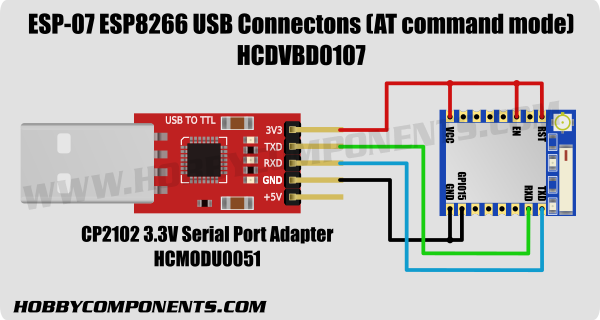
Diagram Esp Floor plans

grblpinout laatste versie

PIR Sensor Datasheet Pinout Specifications Working Homemade Circuit
Post a Comment for "Esp12 Pinout"